How to assemble a Cantilever
1. SAFETY MEASURES
- The personnel responsible for assembly and for the use of the equipment is required to operate in the respect of the existing laws for the prevention of injuries.
The personnel responsible for the assembly is required to complete the assembly with all the safety elements foreseen in the structural project and the personnel who will use it cannot modify in any way the original equipment.
- The user, before beginning to use the equipment that accompanies this booklet, is required to identify all the safety risks and all the measures to adopt with respect to the existing laws for the prevention of injuries, based on D.Lgs. 9 April 2008, n.81.
- In particular, the risk analysis must take into consideration:
- the site of the equipment’s installation
- the function of the equipment
- the personnel who uses the equipment
- machinery, or similar, that services the equipment
form, type and size of the work loads
2. GENERAL RULES FOR SAFETY DURING ASSEMBLY
- The personnel responsible for assembly is required to operate in the full respect of the existing rules to prevent injuries.
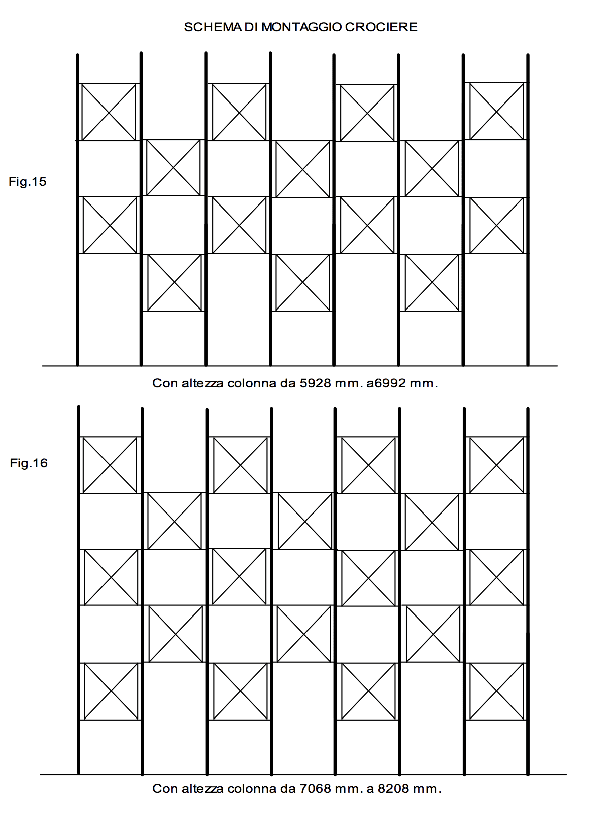
- The personnel responsible for assembly is required to complete the assembly with all the safety elements foreseen in the structural project. Special attention must be applied to the respect of the positioning of the bracing (see Figs. From 12 to 16).
The assembly levels of the arms are on page 2, the fourth row from the bottom; these levels must be respected because their variation could give a different total deflection value. In particular, the deflection increases if the first arm is assembled higher than foreseen:- quota of the first arm measured in mm from the arm loading level starting from the pavement
- step or inter-axis between each arm
- gap of the last arm, the distance in mm from the loading level of the highest arm to the end or the top of the column
The carrying capacity of the pavement of installation must be verified both for the values of the average load and for the values of the punctual load in correspondence with the support points of the equipment (support base).
The support base must be fastened to the pavement in two or three points (as foreseen unless indicated differently by the designer of a structure) to prevent its casual movement and consequently change the alignment of the bases.The planarity of the locale’s pavement surface must be within the following values, measured both in the longitudinal and transverse sense: for lengths up to 50 meters + 10 mm, for lengths up to 150 meters + 15 mm, for lengths greater than 150 meters + 20. In the case of a deviation from the above-mentioned values, one must intervene with the positioning of opportune levelling shims.
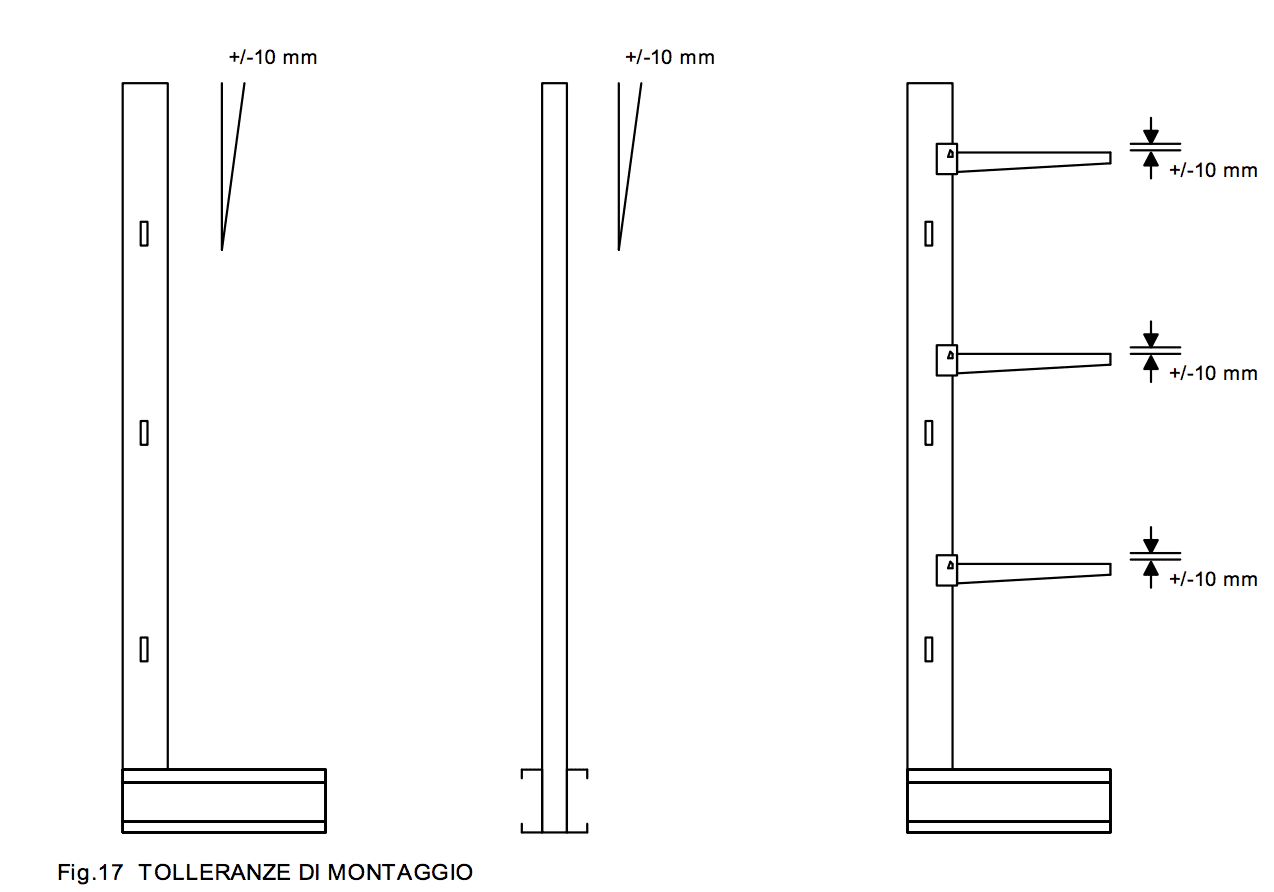
- At assembly (unloaded column) the vertical position of the columns (measurement of the movement from the vertical of the center of the superior extremity of a column with respect to the center of the inferior extremity) measured both in the longitudinal plane (plane in the direction of the bracing) and in the transverse plane (plane in the direction of the arms) must be within the following values: longitudinal movement + 10 mm., transversal movement + 10 mm.
- The tolerance quota between the loading surface of an arm and that of the consecutive arm destined to support the same load must be within + 10 mm. for equipment for manual use.
- At the end of assembly and before the racking is put into use, the signs that indicate the maximum allowed carrying capacity (carrying capacity signs) must be hung. The users of the racking must be informed of these signs.
- At the end of assembly, it is necessary to force the connector of the arm so that it adheres as much as possible to the column. This can be done with a settling strike to favor the definitive positioning of the pin with respect to the anterior side.
3. CORRECT RULES FOR USE AND MAINTENANCE
- The personnel responsible for the use of the racking is required to operate in full respect of the existing rules for the prevention of injuries.
- The personnel responsible for the use is require not to modify in any way the existing equipment.
- The personnel responsible for the use is required to respect the indications of the maximum allowed carrying capacities (carrying capacity signs), of which they must be informed.
The personnel responsible for the maintenance is required to periodically check that the tolerances of the equipment indicated in points 5.5 and 5.6 are respected.
The personnel is responsible for carefully checking the integrity of all the arms and the correct position of the pins with respect to the columns. The operation is obligatory and must be done at least after the first two or three cycles of use of the arm.The personnel responsible for maintenance is required to substitute the damaged elements and to verify that the carrying capacity signs are kept in place and are clearly visible with the indications of the maximum carrying capacities allowed.
4. PRACTICAL PROCEDURES FOR THE ASSEMBLY OF CANTILEVER RACKING
- The personnel responsible for assembly must use both the suitable safety equipment (helmets, gloves, shoes, safety harnesses etc.) and lifting equipment supplied with specific safe and authorized hooks, pulling devices etc.
In the case of fork lifts, these must be equipped with specific hooks approved by the producer and ISPESL.
- Fork the flat side of the column, balancing it with care (Fig. 1).
If single-sided, put it on two thicknesses and put it vertically on the base. If double-sided, lift it to a height that allows it to be rotated easily and set it on the ground on its side, being careful to accompany it until it turns laterally.
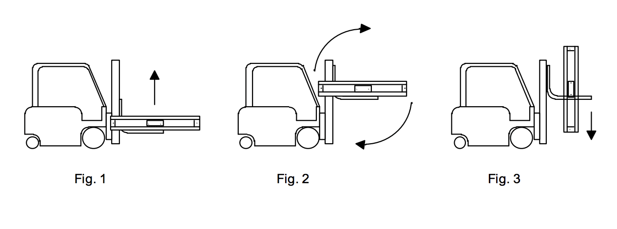
- Pass a harness around the column below the ears (Fig. 4) or eventually below a pin positioned at a height that allows the fork lift to lift the column, taking the length of the harness into consideration.
- Position the fork lift perpendicularly to the column, inserting the fork opposite the base of the column into the free hole of the harness and lift decisively, accompanying the movement of the column (Fig. 2 and 3) until it is 10/15 centimeters from the ground.
- Position the column in the exact assembly point and fasten it to the pavement with expansion bolts. Carefully slip off the harness, free the column and proceed with the same procedure for the following column.
- Position the second column and connect it to the first with the lowest bracing.
- Assemble the bracing based on the height of the column, as per attached designs.
- Assemble all the columns tightening the screws of the bracing once the verticality of the columns has been verified.
- Before fastening everything to the pavement, check the verticality of the column on the lateral plan and eventually proceed with the levelling of the bases until it is obtained. It is sufficient (except in the cases of pavements with extreme inclination) to do the levelling under the base in proximity of the fastening points and, for the single-sided structures, in correspondence with the middle of the base. If the assembler does not have the adequate equipment (optical or laser level), a fast and practical method to verify the verticality of the column is to position a normal bubble level on the superior wing of the base to check its horizontality.

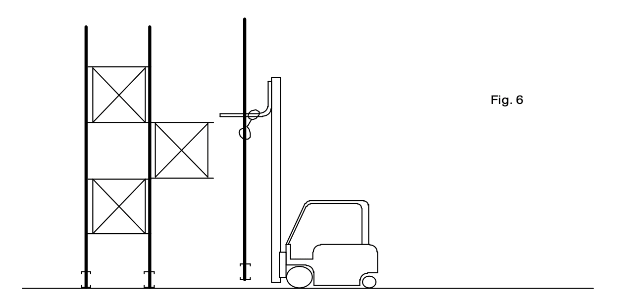
- Begin, therefore, starting from the top, the assembly of the arms at the heights foreseen with the use of a platform. In alternative, one can use a cage lifted by the fork lift. Inside the cage, the assembler can stock all the arms to be assembled and he can work in complete safety. To allow the easy insertion of the pin, the arm must be kept slightly elevated so that the inferior sides of the holes of the columns and arms coincide. Once inserted the pin, the arm must be positioned by striking the arm near the connector in a downward motion with a rubber hammer.

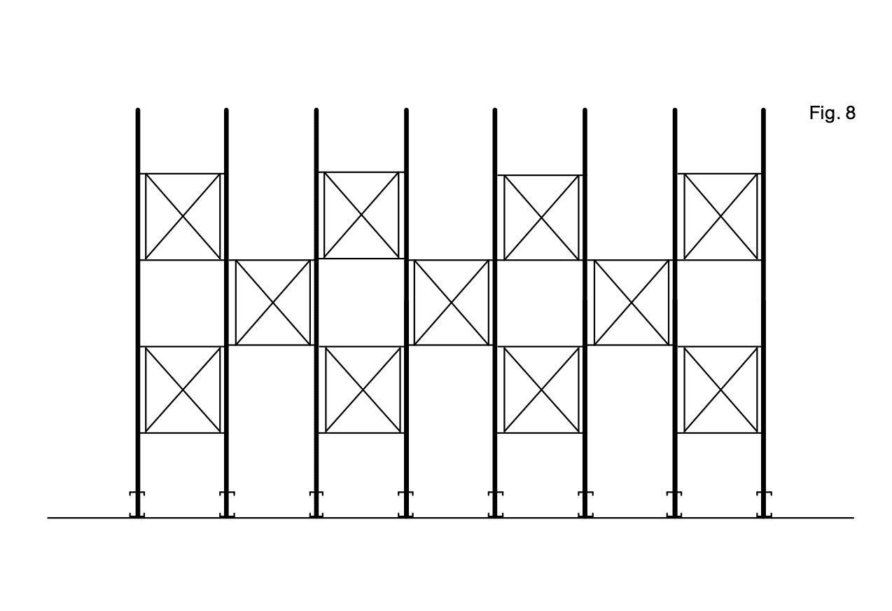
- Fig. 7 shows the procedure that allows assembling the columns at the prescribed intervals and in the correct verticality. Use the bracings to obtain a continuous row in correspondence with the first level. Once the assembly of the row has been completed and after having proceeded with the fastening of the bases, remove the bracings and move them in correspondence to the prescribed position. The result of this operation (illustrative for column heights that are with the assembly type indicated in Fig. 14) is shown in Fig. 8. At the end of this operation, always check the verticality of the columns.